
Variometer
Developing a variometer for paragliding with custom PCB and screen
Quick Facts
- Role
- Embedded + hardware (PCB, firmware, estimation, simulation)
- Team
- 1 people
- Domains
- EmbeddedControlHardwareSensors
Key Decisions
- Kept a single firmware codebase and added a Linux simulation layer to speed up debugging and iteration.
- Combined IMU + pressure sensing via filtering (Madgwick + Kalman) to get stable climb-rate estimates.
- Implemented efficient partial E-Ink updates to keep power draw low while staying readable in flight.
Results
Tech Stack
About This Project
Variometer for Paragliding
Overview
This is the largest project I have worked on so far. It started as my Maturarbeit, where I built a variometer — a device that helps paragliders estimate their vertical velocity when flying in thermal air. The first version was based on an Arduino and used a Kalman filter to estimate the climb rate from pressure and acceleration data.
During my gap year, I completely rebuilt the project from the ground up. The new version features a custom PCB, E-Ink screen, GPS, speaker, and Bluetooth. It is now a fully functional embedded device that can record flight data, visualize it in real time, and connect to external flight apps.
Key Features
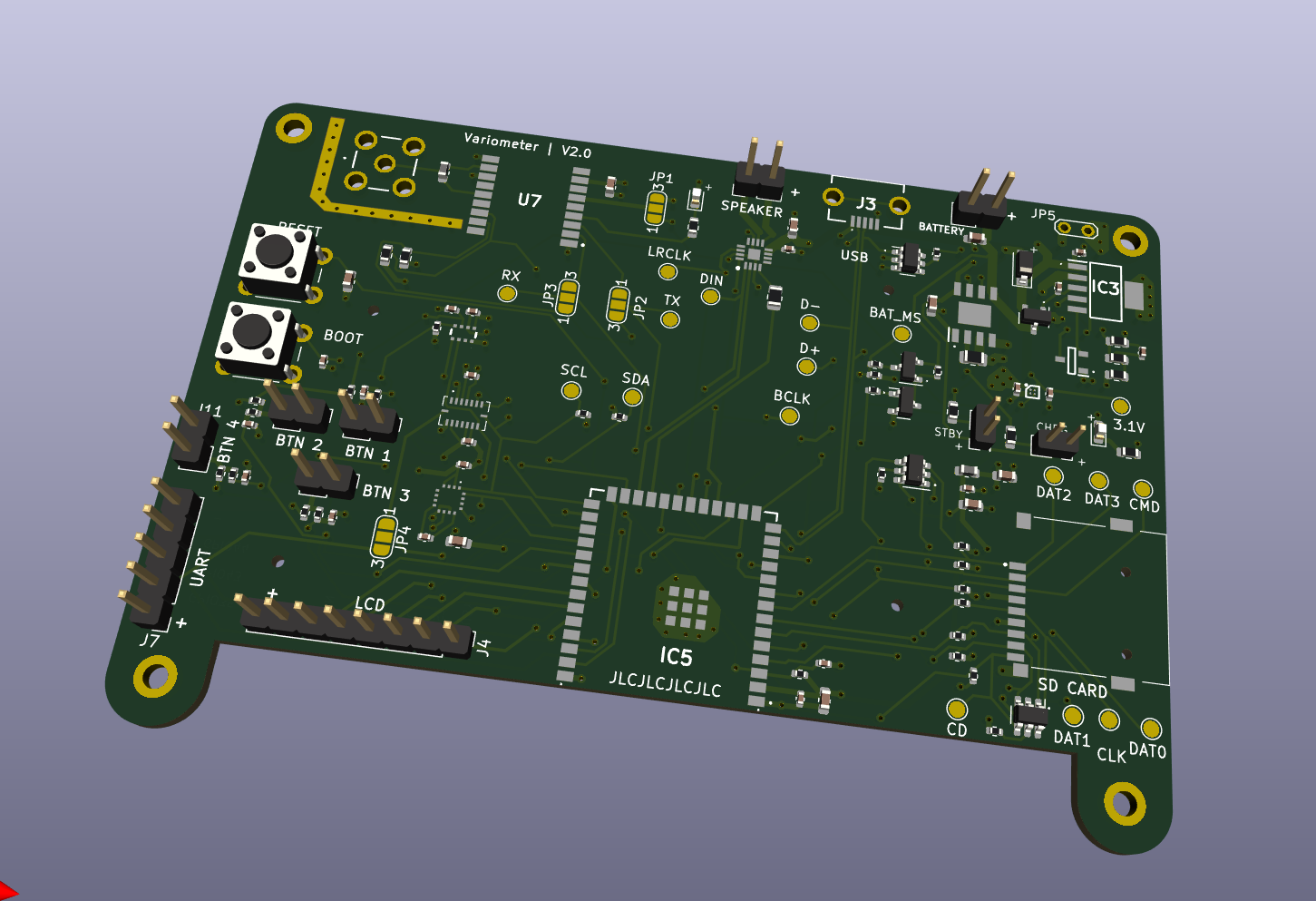
- Development of a custom PCB with surface-mount components
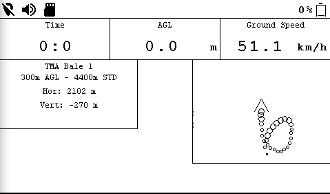
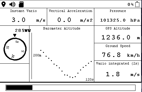
- E-Ink screen for displaying flight data, fully implemented from scratch
- Modular widget system for flexible on-screen layouts
- Kalman filter for accurate vertical velocity estimation
- Custom-designed case with built-in navigation buttons
- SD-card logging in the IGC flight record format
- Bluetooth connection to flight apps such as XContest
- Integration of GPS, battery monitoring, and speaker output
- Linux simulation using the same firmware for faster development
Technical Implementation
The project consists of three main parts: the software, the hardware, and a Linux simulation.
The software is written in C using the ESP-IDF framework for the ESP32 microcontroller. I used FreeRTOS to divide the system into separate tasks, such as sensor reading, screen updates, and data logging. Sensor fusion is based on a Madgwick filter for orientation estimation, while a Kalman filter combines acceleration and pressure data to calculate the vertical velocity.
Flight data is stored on an SD card in the IGC format, and nearby airspaces are shown based on GPS position and altitude. The E-Ink display is driven by custom rendering logic, handling partial updates efficiently to save power.
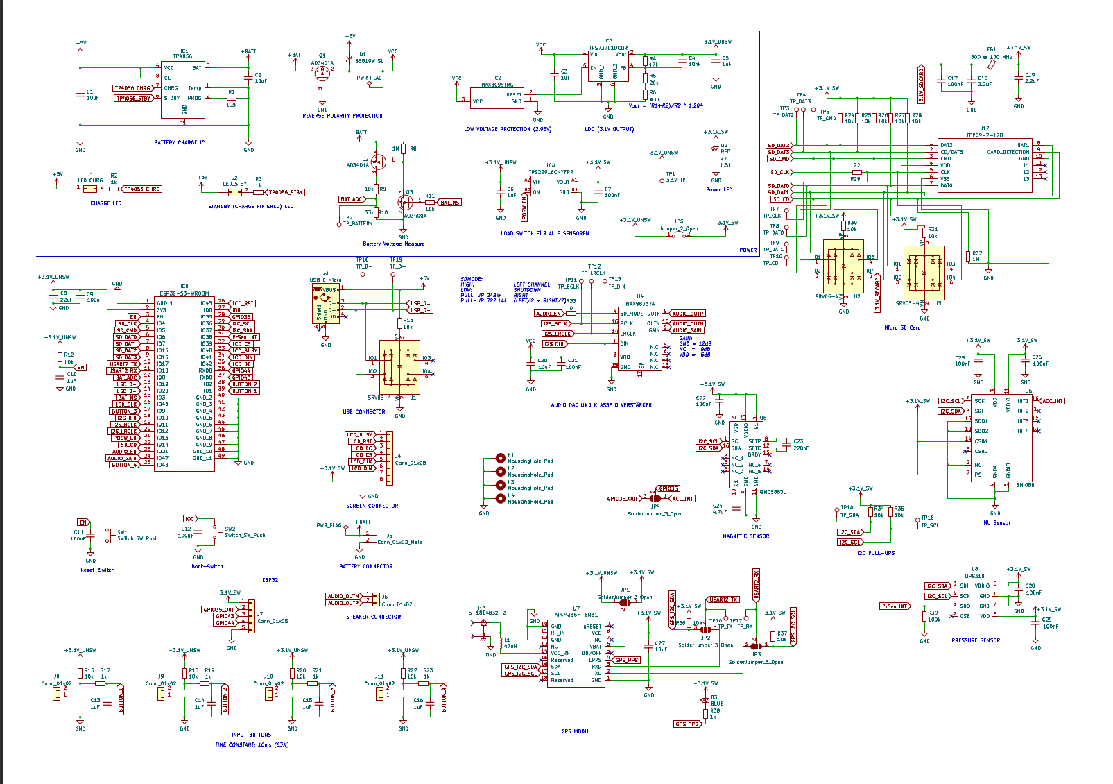
The hardware was designed in KiCAD and includes the ESP32 microcontroller, GPS module, 9-DOF IMU, barometric sensor, and power management. The PCB layout features proper 50-ohm impedance matching for the GPS antenna and connectors for the screen, battery, and USB-C port. After finalizing the electronics, I designed a 3D-printed case with integrated navigation buttons, which makes the device easy to use in flight.
To speed up development, I created a Linux simulation that runs almost the same code as the embedded firmware. Only the hardware drivers are replaced with simulated ones, allowing the device logic and display to be tested directly on a computer. This approach made debugging and development much faster while keeping a single, consistent codebase.
Challenges Overcome
- Designing and manufacturing a reliable custom PCB
- Implementing a complete E-Ink rendering system from scratch
- Creating a widget-based UI on an embedded platform
- Building a functional case with navigation buttons
Future improvements
- The goal is to publish this variometer and try to sell it to the market
- I always wanted to include BLE for the variometer, but never got it to work properly
Technologies Used
- C – Firmware and simulation
- ESP-IDF / FreeRTOS – Microcontroller framework and task management
- KiCAD – PCB design
- 3D printing – Case design and prototyping
- Linux – Simulation environment